

Every 3-4 years, a commercial kitchen technician is electrocuted and dies. Every week we come across instances of suspect wiring and dangerous installations. Nothing we do is worth getting hurt for. Work safely – for you, your colleagues, your customers and your
Nobody sets out to cause injury or death. But we work in a field where negligence, or not carrying our job out correctly, can and does lead to death. Compliance is not discretionary – it is absolute.


Index - Links to sections:
RESPONSIBILITIES AND COMMUNICATION
TRAINING, COMPETENCE AND EVALUATION
USE OF LOCKING OFF DEVICES, LOCKS AND LABELS LOTOTO
PROVING DEAD ISOLATED EQUIPMENT OR CIRCUITS
PLAN & PROCEDURE FOR LIVE ELECTRICAL TESTING
RESTORATION OF SUPPLY ON COMPLETION OF WORKS
CARRYING OUT ELECTRICAL SAFETY TESTS
Appendix B - Guidance on selection of protective, isolation and switching devices
Appendix C - Customer communications
Appendix D - Equipment handover form
Appendix E - Calibration and testing policy
INTRODUCTION
Tragically, Electricity is the regular cause of fatalities in our niche industry – this in direct contrast to Gas where, to the best of our knowledge, there has never been a fatality. One striking contributory factor: astonishingly, there is no regulatory requirement for professional competence - you can set up as a sole trader or as a company and carry out electrical works on heavy-duty, 3-phase electrics with no training and no assessment. No wonder there are deaths.
We take three steps to ensure we don’t join the statistics
1. Training: no-one will be allowed to work on electrical equipment unless trained, assessed and signed off for the risks which they may encounter.
2. Equipment: we provide the right test equipment and PPE to ensure you have the tools to carry out the job safely
3. Assessment and Audit: we have a comprehensive audit regime, to check that the work we do and the technicians who do it are working safely. And if found wanting – these individuals are not just risking their skin but the livelihood of their colleagues – corrective action will be taken.
There is one procedure which might have saved the lives of the three most recent fatalities – TESTING OUT. We’re all aware of Lock-Out-Tag-Out. The final part of that process – Testing-Out is ensuring that you haven’t accidentally isolated the wrong appliance, someone hasn’t wired it in wrong – or that it doesn’t have additional supplies. Make sure, before you start work, that the equipment is Dead.We NEVER Work Live but, under strict conditions, we may TEST LIVE. Those conditions are : there is no other effective way of ascertaining the fault, you are competent to carry out the work, there is no risk of interference from others – and you are wearing the appropriate PPE to prevent accidental contact.
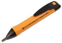
Volt Sticks
A further aid towards electrical safety which MCFT have mandated is the use of volt-sticks – not as test instruments, but as sensors of live current before touching any appliance. Technicians should develop the “Safety Check” reflex to use a voltstick before touching any part of an appliance – whether believed to be isolated or not.
In addition to training and the discipline of applying that training, every day, every job, there is one other “safety net” which might just save you if you have an incident: RCD or RCBO protection.
Unfortunately RCD protection, usually on the distribution board, is not down to us. Whilst commonly available, not particularly expensive and strongly recommended in recent editions of the wiring regulations, BS7671, our perception is that 75% of the kitchens we work in are not protected by RCDs.
Two things flow from that:
1. Make it your business to know if the circuit you are working on is protected
2. If it isn’t, record it on your job sheet – and point it out to the responsible people on site, it might save their lives as well as yours.
Nothing we do – NOTHING WE DO – is worth getting hurt for. If you are ever unsure on anything you are required to do you must ask, do not continue without checking. Come home safe, every day. And make sure those around you do the same.
This document is the result of extensive research and consultation and with the brief that we will only include those actions which we believe are appropriate, proportionate and enforceable; it will be regularly reviewed and enhanced and is testament to our collective commitment to working to the highest standards.
David Meacock
July 2025

2023 HSE Prosecution
In early 2013, McFarlane Telfer Ltd was asked to quote to supply and install a replacement Sink Waste Disposal Unit at BMI Bishopswood Hospital, which they duly carried out in May 2013. After a single further maintenance visit in May 2014, other organisations took over the maintenance of the catering equipment at the hospital. Tragically, in December 2017, a catering technician working for one of those successor organisations on the appliance was fatally electrocuted.
In 2021, the HSE brought charges against four parties, and against McFarlane Telfer for failing to follow manufacturer’s instructions that the unit be installed by a “Qualified Electrician” and protected by RCD.
On Monday 22nd May, the jury found McFarlane Telfer guilty of breaches under the Health and Safety at Work Act; sentencing took place on 3rd October and MCFT were fined £70,000.
The court heard that the waste disposal unit had a long list of design and manufacturing defects and should never have been in the market – evidenced by two in-field modifications actioned after the incident and, in April 2021, the eventual global recall of all appliances, recognising that there were fundamental and irremediable flaws. These points were accepted in full by the manufacturer before sentencing. We are not aware of a similar catering equipment recall in the last four decades.
As accepted during the trial, if an RCD had been identified as a necessary control measure, it should have been fitted by the manufacturer. It was also beyond the competence and scope of Catering Technicians to install an RCD. At this time, no other manufacturer required the same – the manufacturer, did not even require on any of their other models – and there was no prior communication of the requirement, or the reason. RCD’s should only be required as secondary protection, not specified because an appliance is fundamentally dangerous.
In common with many others, the manual required that the equipment be fitted by a “Qualified Electrician” – whereas in practice, and accepted by the court, the industry accepted that Catering Technicians have a different remit and only carry out the final connection to services provided by others. (See recent resulting industry clarification and infographic in Appendix H – Demarcation of Responsibilities).
In conclusion, the fact pattern involved in this conviction was unique and device-specific – there were no findings of general fault in relation to the manner in which McFarlane Telfer runs its business from a safety perspective – the judge commented that MCFT was “a fundamentally decent outfit” and the joint experts made a number of recommendations on improvements the catering equipment industry should consider, including the identification of commercial kitchens as Special Locations, requiring RCD protection. Prior to the guilty verdict, MCFT had been campaigning for a number of years for the improvement & implementation of additional regulation and will continue to do so, taking on board any learnings which have already been identified & implemented following this tragedy, and ensuring that lessons are disseminated throughout the industry.
RELEVANT UK LAW
Electricity at Work Regulations 1989
- BS7671 Wiring Regs; current edition 18th +A2+A3
- IET Code of Practice for Inspection & Testing of Electrical Equipment, 5th Edition
- Provision and Use of Work Equipment Regulations 1998
- Management of Health and Safety at Work Regulations 1999
These set out mandatory standards including that electrical installations and equipment
- Must only be worked on by suitably qualified and equipped personnel
- Must be inspected at appropriate intervals
- Must be risk-assessed: in the event of risk, measures must be in place to mitigate
Duty holders and respective responsibilities
What is not fully spelt out in the regulations, is the clear apportionment and communication of responsibilities (including ensuring that respective circuits are connected). Section 4.2 of the IET In-service Inspection and Testing CoP confirms that connected equipment is not the remit of the customer’s fixed-wiring contractor, whilst everything to and including the isolator is.
Our view IS clear – we are responsible ONLY for
- The electrical safety and performance of the appliance
- The safe and appropriate connection to appropriate and safely isolated services provided by others
- Testing, during interventions, that the appliance is safely and appropriately connected to those services. We will carry out these tests unless formally requested not to.
It is the respective duty-holder’s (facility owner or operator) responsibility to ensure that they have in place
- Knowledge of the regulations
- Knowledge of the electrical assets within their control and the appropriate governance regime and procedures to have installed and to maintain those assets safely.
- Appropriately qualified and equipped personnel to monitor and report at appropriate intervals
- The means to communicate same and any other relevant information to sub-contractors when working on electrical assets
Given current industry working practice and the power dynamic, we do not feel it would be realistic to require proof of same – the best we can do is to clearly communicate the basis under which we undertake our work and the consequent necessary trust in our customers’ standards and care for their sub-contractors. Equally, we hope they will be understanding if we decline work which is beyond our competence or scope.
In 2024 CEDA produced the Code of Practice for Electrical Work in Commercial Foodservice Facilities to establish clear guidance on the clarification of responsibilities, a common regime of working practices and the level of electrical competence required by foodservice equipment technicians. Appendix H – Demarcation of Responsibilities for further details.
PREFACE
Purpose
- To assist the work of MCFT technicians in respect of controlling health and safety risks arising out of electrical fault finding, testing and remedial work. (this is not a technical how-to guide – no-one will fix a fridge by following this manual)
- To document a systematic and thorough approach to the subject
- By reference to regulation and best practice to inform customers as to the basis of our approach
Roles and responsibilities
- The Technical committee is responsible for the content of this Manual and its progressive improvement through the periodic (min annual) review process
- The Team Leaders (TL) and Technical Committee are responsible for ensuring the implementation of this manual and for ensuring the competence of the MCFT technicians in respect of implementing the requirements – this is to be covered off during induction for all new field operatives
- The MCFT technicians are responsible for adhering to the instructions given in this Manual and making their Team Leader aware immediately of any area they are unsure of – technicians must sign to say they have read and understand this manual content
- Recognise your limits: MCFT technicians are not equipped, trained or competent to carry out work beyond connection to services provided by others – we do not run new supplies or change isolators.
Escalation Process
In the event of an issue on site where advise is required immediately follow the below process
- Internal escalation
- First stage - Technician to Team Leader
- Second stage - Team Leader to Technical Support Lead
- Final stage - Technical Support Lead to Director
- External escalation
- Customers point of contact – also escalate the issue to your Team Leader
WHAT ARE THE HAZARDS
Primary
- Thought to be dead but actually live
- Known to be live but those involved do not have the adequate training or appropriate equipment to prevent injury, or they have not taken adequate precautions
- Faulty or damaged test equipment
- Lack of communication – ‘I thought you isolated the supply’, ‘but I thought you did
Secondary
- Lack of safety controls on current circuits – RCD’s
RESPONSIBILITIES AND COMMUNICATION
- It’s clear that responsibilities and communication of hazards are a weak spot in current guidance.
- By what means, do the manufacturers’ requirements become known to the customer when purchasing equipment?
- What liaison is there between site electrical contractor and maintenance provider?
- Is there ever access to documentation on installed equipment, current wiring inspection or previous maintenance records?
The answer in all cases is little or none.
For this reason, we have instituted procedures – clear communication on requirements at time of quote, clear signed acceptance of duties at time of commissioning and handover – and we need our technicians to be mindful, not just of their responsibilities, but of communicating (and documenting on job sheets) their responsibilities.
If an isolator has become damaged, it may be the customer’s responsibility, but we have a duty to inform. Picture the situation in court: “you would have observed the danger posed by the broken isolator and you didn’t think it important to report it ?” It’s actually a specific breach of H&S Law – the duty to report and inform.
WHO IS IN CHARGE?
During flight, there must always be a clear understanding between pilots of who has control of the aircraft. Prior to a flight, a briefing should be conducted that includes the procedure for the exchange of flight controls. A positive three-step process in the exchange of flight controls between pilots is a proven procedure and one that is strongly recommended. When one pilot wishes to give the other pilot control of the aircraft, he or she will say 'You have the flight controls.' The other pilot acknowledges immediately by saying 'I have the flight controls.' The first pilot again says 'You have the flight controls.' When control is returned to the first pilot, follow the same procedure. A visual check is recommended to verify that the exchange has occurred. There should never be any doubt as to who is flying the aircraft.
Internal Communication
There are similar risks from poor allocation of tasks and communication within teams.
At the extreme end, two people working on equipment, both thinking that the other has carried out the isolation. This situation, in one form or another, is regularly reported in the Safety Press, usually as the result of a fatality. One person must take ownership – “I have control, you have control”
At a lower level, technicians assuming tests have been carried out by others. If you’re working on an appliance, you MUST carry out your own safety checks.
Escalation
The risks associated with electricity are such that, having observed a significant risk, it is imperative that action is taken – which implies firstly safe isolation and protection from interference and secondly, documented reporting to a) customer responsible parties and b) MCFT senior team.
Only when you have done so, have you passed on the risk.
TRAINING, COMPETENCE AND EVALUATION
Training
Although there is no statutory requirement and many in the industry are qualified “by experience”, MCFT will ensure that anyone asked to perform a role, has training and competence in that role. Further, the commonly accepted measure of electrical “knowledge” is the C&G 2382 18th Edition course – which informs on the regulations (BS7671) but helps neither with electrical working safety, electrical diagnostic and fault-finding nor in the specifics of our working environment and responsibilities.
Consequently, MCFT Electrical training for technicians will be as follows:
MCFT Routes to, and maintained, Electrical Competence
We have carried out an evaluation of what would be appropriate in the way of training, given the range of tasks and risks involved in our role. In the complete absence of useful official guidance by the regulators, we have also had regard to comparable qualification such as Part P (100hrs) https://electrical.theiet.org/media/1150/electrical-qualifications.pdf
All training is carried by qualified trainers; all coaches and Team Leaders have appropriate training and skills, critical sign-off and assessments are carried by an external provider, accredited to LCL Awards.
Auditing & Assessment
To ensure MCFT technicians are competent, working to best practice and the high standards expected, post-visit site audits will be carried out, and assessments will also be carried out during a technician’s site attendance
- All technicians’ work will be audited annually by inspection following a work visit
- All technicians will be assessed by face-2-face review annually
- Results will be recorded and stored on the One Drive along with any follow up actions
- Audit and assessment records will be made available for our customers to review
Proof of competence is not just a matter of skills training or a certificate, it is verification of the consistent, demonstrated use of those skills.
TOOLS AND EQUIPMENT
- Technicians must only use electrical test instruments and leads that are supplied by the company
- Calibration of equipment – technicians must not use uncalibrated or defective equipment and must inspect equipment immediately before use
- Technicians must ensure tools are in a good condition and are compliant before use – hand tools must be compliant with BS EN IEC 60900:2018 or VDE approved
- Technicians are responsible for the management of calibration expiry dates; the technician must inform the QHSE manager that their test equipment is due to expire 6 weeks before the calibration expiry date – loan test equipment will be provided while your own equipment is being calibrated Technicians will have access to there folder on the One Drive which will have their up to date calibration certs.
Testing of 13-amp sockets Good Earth Test
- For all equipment supplied from a 13-amp socket, before commencing any work, the technician shall test the incoming Supply socket using the tester supplied by the company. In the event of the tester showing a fault the matter must be reported to the MCFT customer contact and a note recorded on the job sheet, the technicians team leader is to also be notified
- No further work will be undertaken by the technician using the defective Supply socket until the fault has been rectified and retested to prove functioning correctly
- Tools and equipment provided are in accordance Guidance Note GS38
- Technicians to sign and demonstration understood
- Training will be provided when the company issues new test equipment
FUSES
Always check correct fuse size in plugs and spurs on the wall to make sure they are rated correctly for the appliances they are supplying.
How to work out the fuse rating
The calculation is watts divided by volts equals amps. After you have calculated this, multiply by 1.25 to arrive at the safe value and choose the nearest fuse to match - always go up to the next size, not down.
Example:
Kettles have a wide range of wattages depending on if it is a slow boiling kettle, or a rapid boiling kettle: let’s say we have a kettle with a 2200 Watt element, the calculation would be as follows:
- 2200 watts kettle / 240 Volts UK (NB UK Regs say 230v +6%, -10%)
- 2200/240 = 9.17 amps
- 9.17 amps x 1.25 = 11.46 amps
- Kettle recommended fuse rating is 11.46 amps
- Next fuse up is a 13 amp so we would fit a 13 amp to this kettle
(NB a 3000W kettle, with a safety margin, would need a 16amp supply & fuse…)
RCD’S AND RCBO’S
Following a recent fatality in a commercial kitchen, the HSE have issued strong guidance that
- there are instances where manufacturers’ instructions to protect devices with RCD’s have not been complied with
- a risk evaluation would extend that requirement for an RCD to the majority of metal-cased (Class 1) appliances with electrical connections – practically all appliances in commercial kitchens.
There has apparently been no reported fatality from electrocution from a circuit protected by an RCD or RCBO breaker.
Note the emphasis in the following IET guidance on the risk evaluation of circuits with socket outlets:
In order for the omission of RCD protection to any socket-outlet on the basis of risk assessment to be permitted by Regulation 411.3.3, the risk assessment must determine that the RCD protection is not necessary. The risk assessment must be documented and a copy of it must be attached to the Electrical Installation Certificate or (where applicable) Minor Electrical Installation Works Certificate covering the installation of the socket-outlet.
The person who prepared the risk must be prepared to justify his or her conclusion that RCD protection was not necessary, possibly in a court of law, especially if someone was killed or injured as a result of the RCD protection being omitted.
(Source IET Guidelines, comment on BS 7671:2008+A3:2015)
The point being that risk assessment would be to support situations where an RCD is NOT required, rather that justifying when they are required. And interpretation of this guidance is that this Risk Assessment over-rides any previously assumed latitude not to have to upgrade legacy systems.
Given the increased risk from heavier duty appliances – and their ongoing vulnerability from daily wear-and-tear and susceptibility to misuse – it is difficult to envisage successful arguments against RCD protection of circuits providing power to commercial kitchen appliances.
Historically MCFT have taken the industry view that our responsibility is the last metre of connection to the isolated supply on the wall.
The 18th Edition indicates that installation of RCD’s is a requirement for new installations and there is no over-arching obligation to retro-fit. However, there is a requirement to review risk – and where appropriate, to uprate installations to include RCD’s.
MCFT’s assessment would be that any kitchen appliance - given the exposure to wear & tear, users, water, cleaning, maintenance etc – falls into the category of high risk and therefore should be protected by an RCD or RCBO and the standard for our applications is RCD = 30mA & RCBO= 30mA Type C. (Type B – Domestic – may lead to nuisance tripping).
Some equipment, such as accelerated cooking ovens, have a high inrush current and can cause an RCD to trip even if there is no leakage. Follow manufacturer's instructions for the correct selection. In the past some manufacturers have stated not to use RCDs with such equipment, this stance has now changed and they will specify the correct rating.
It is the responsibility of MCFT to give guidance to the customer on the RCD/RCBOrequired, and to make sure it is in place before commissioning the appliance. It is the responsibility of the customer to install the RCD/RCBO.
MCFT will:
- Advise an RCD/RCBO is required when equipment is quoted (as part of gas/electrical/water/waste services requirements)
- Check the RCD/RCBO is installed before we carry out the installation of equipment– if the RCD/RCBO is not correct or verifiable do NOT connect the equipment
- During routine maintenance (and where accessible and permitted by the customer) - test and ensure the RCD/RCBO is working (not held in by grease or dust)
During a first (major) annual service - verify (if access is not possible, noting to the customer) that the correct RCD/RCBO is in place, tested and working – if there is no RCD/RCBO in place advise the customer of this requirement, it is the customers responsibility to contact their electrical contractor – MCFT will not install the RCD/RCBO
EARTH BONDING
Whilst MCFT will ensure appliances are appropriately earthed and record earth continuity readings, supplementary earth bonding of stands, tables and sinks, in accordance with CEDA guidelines below, should be carried out by the site electrical contractors; this is not a service MCFT are equipped or qualified to offer. MCFT will comment on whether there may be a recommendation, during the major annual service visit.
Catering Equipment Distributors Association Guidelines On Earth Bonding 2013
The belief has been that any gas catering appliance with a metal structure requires equipotential earth bonding but this is not the case: this bonding is only required where an electrical appliance is going to be used on a metal surface and if that appliance had a fault which could introduce voltage to that metal surface a potential for electrical shock was introduced.
The above would normally be a fixed metal work surface, not a mobile table, a fixed surface of mild or stainless steel construction. If say a slicer is going to be used on this surface, then this work surface is where bonding is required.
- There is no requirement for a purely gas cooking appliance to have any supplementary earth bonding.
- Commercial catering appliances of a metal construction are not considered "extraneous metalwork" therefore, no bonding is required. If the appliance has say electric elements or motors, then this will be supplied with a single or three-phase supply along with an earth conductor. No requirement for extra bonding.
- Any appliance that uses electricity as well as gas will already have an earth wire attached to it by way of its mains lead.
- A mobile table used for loading and unloading an appliance does not need any bonding.
- A Table between appliances used for loading and unloading does not require earth bonding.
- A fixed table that is used for the operations of electrical equipment however should be considered to have a bonding wire fitted. There is a chance that a mains lead to a portable appliance could be damaged and introduce the risk of making the metal work "live".
- If there is a fixed table that is screwed and fixed in place to a concrete floor or wall, then an earth bond should be fitted. This is because the concrete may be damp and have an earth resistance path, thus if this was the case and an earth fault occurred, it would be unlikely that the fault current would be sufficient to activate the Residual Current Device protecting the circuit. The table would be live and an electric shock potential introduced.
When any item of equipment is going to be supplied, we as suppliers or installers, should ensure the site is surveyed and the client made aware of what electrical supply is required. We should only then connect when satisfied that supply is correct. To conclude, any supplementary earth bonding, the client believes or is led to believe is required, it is for them to arrange with a suitably qualified electrician.
Note from the ECA web site: Earth Bonding in Commercial Kitchens. Guidance document. August 2013
"Supplementary bonding of metal surfaces etc. is not a specific requirement of BS7671. The designer of the electrical installation may, however, perceive there to be an increased shock risk in that particular location and specify additional earth bonding, which has to be installed by a qualified person"
Earth Continuity – Important notice
- NEVER falsify readings – clearly record your results and add your initials
- Make sure any installation connection is tested and actually going to earth (the cable coming out of the wall is actually earthed, not just hanging there – see Good Earth below)
- Verify any earth bonding of metal tables, brackets or shelves with appliances incorporated or just on them e.g. slicer, microwave or mixer.
- Physical inspection – does bonding look secure?
- Meter for earth insulation and record reading
- Comment on job sheet if table needs attention – rectification work to be carried out by others
Note: MCFT will not be checking tables or bracketry which does not carry electrical equipment.
GOOD EARTH TESTING
(Earth loop impedance (Ze) taken at the appliance/equipment supply, not the incoming/distribution board supply as you would get on a fixed wiring cert).
We carry out this test to prove that the incoming earth supply to the equipment/isolator/socked is sufficient. We have taken this stand in the industry to make sure that our equipment is connected to a GOOD EARTH as, in our direct experience, there have been multiple instances where appliances are connected, in good faith, to circuits which don’t go anywhere or are totally missing – at least one resulting in a fatality. When we leave an appliance ready to be used by our customers, our duty is to ensure that it is safe to use; if we are not sure of that, we leave disconnected and document our observations.
By completing this test, we are confident that there is an earth which, in a fault condition, would cause the RCD/RCBO to trip. If when carrying out this test the earth reading is poor, or even not there at all, the appliance must be left disconnected, Isolated & the customer advised that support is required from their electrical contractor to investigate and remedy.
For good earth testing MCFT will use a Martindale socket tester to establish low earth loop impedance – handover documentation will include mention that there is a small risk of nuisance tripping during this test & MCFT will continue to carry out this test unless the site come back to MCFT to specify that they do not want this done. At this point, MCFT will confirm that the customers takes full responsibility for the safe electrical supply to the appliance. In the event of a poor or missing result, MCFT may ask to see a copy of the current fixed wiring test results.
NB It’s essential that supplementary bonding is removed whilst this test is carried out – secondary bonding has been shown to mask serious defects in the Primary (CPC) Protection.
INSTALLATION OF EQUIPMENT
New Equipment
- Connecting to an incoming power supply – this must be proved to be correctly specified and sized accordingly for the appliance being installed, and adequately protected by means on an RCD /RCBO before the appliance is connected – 3 phase supplies must have all 3 phases present
- If there are any concerns escalate to the Field Technical Manager
- The customer must confirm that an adequate isolation point is available for the appliance to be connected to
- The customer must supply, where necessary, gas, electric, water and drainage for the appliance
- The installing technician must ensure the handover paperwork has been completed and the appliance is installed to the manufacturer instructions – advise the users responsibilities for commissioning and use (e.g. season Bratt-pan, ensure inter-locked vent system etc)
- A copy of the manufacturer’s instructions is to be left with the customer
Pre-Used Installations
- Obtain the manufacturers installation manuals/instructions – which may include warning notices to customers
- Always install the equipment to the manufacturer instructions
- Once installed the technician must carry out comprehensive testing recording any test results on the job sheet
- Advise the user of any responsibilities that must be adhere to for commissioning and use
PRIORITIES: SAFE BEFORE WORKING
In early 2013, we were called to look at a multi-deck chiller unit reported as not working at Hampton Court Palace. We attended, we had not seen the unit before, having come, used, from another site, discovered that a controller was needed, changed the controller and left site, everything working. On Monday 15th July 2013, we received a call to say that there had been a serious incident on site on the Sunday, could we come in for a meeting. It was reported that the room in which this chiller was located was needed for an event on the Saturday. The unit was taken out and then pushed back in on the Sunday. Unusually and against best practice but not against the law, the unit had two plugs and the sockets were at high level. In order to get to them, the chef pulled over a stainless steel table and stood on it; as he put the first plug in and switched in on, he received a significant shock from the second plug he held in his hand – and was thrown off the table onto the floor. He was taken to hospital and kept in overnight but thankfully released on the Monday with a bad burn on his hand. It transpired that, unbeknown to us, the two circuits had been connected, not from the factory but by a maintenance contractor. It was not picked up during our repair visit – not the first thing we might look for but the FIRST and LAST responsibility we have – well ahead of actually fixing things – is that we leave equipment SAFE. Unsurprisingly, we were not invited back.
SAFE ISOLATION WHEN WORKING
When working on an electrical installation, it’s vital that you disconnect it from the live supply and test whether any current is running through it before making a start on the task at hand. In the electrical trade, this process is referred to as safe isolation. Once you’ve disconnected an installation from the rest of the circuit and checked that no current is flowing through it, the system is said to be “dead” (as opposed to “live”). At this point, you can safely start investigating and fixing the equipment. We isolate systems from the rest of the circuit prior to working on them primarily for safety purposes: if part of the installation is still live (i.e., connected to the mains supply), then you and other people on site run the risk of receiving an electric shock and serious burns.
The most common way to disconnect equipment is to use the main isolator switch or unplug the item, which controls the supply of electricity. Once you’ve done this, you’ll still need to test the system properly before you start to carry out any work. This is referred to as testing for DEAD.
Importance Of Isolating The Correct Circuit
MCFT technicians must ensure that when undertaking isolations, any isolation is applied to the intended circuit. There must be no doubt that the point of isolation is correct for the equipment on which work is to be undertaken.
In most cases the point of isolation will be close to the apparatus being isolated and the connection between the isolator and the apparatus is clear. On other occasions the connection between the two points might not be clear. Indeed, the point of isolation might be some distance away and located in a different room to the apparatus being isolated. In these circumstances it becomes necessary to rely on the labelling of the equipment so that the correct isolator can be identified without doubt. If there is doubt, the technician must refer the matter back to the customer recording a note on the job sheet.
Where the connection between the point of isolation and the equipment cannot be physically checked and reliance is being placed on the labelling of the isolator and equipment, the use of a voltage detector for verification of the correct point of isolation must be adopted. This forms part of the safe isolation procedure (proving the system/circuit voltage free) prior to working dead.
Technicians are instructed to use the voltage detector prior to making contact to any parts that had previously been live and are instructed to prove the functionality of the voltage detector before and after use. Technicians must wear the company issued electrical gloves when using voltage detectors.
Safe Isolation Procedure: Step-by-Step Guide
The steps involved in the safe isolation procedure are as follows:
- Obtain the required permission to work on the installation.
- Identify the source(s) of supply.
- Test your voltage detector to make sure that it is working properly.
- Isolate the supply, disconnecting the system from the mains.
- Secure or “lock off” the isolation using your safety padlock, preventing any tampering.
- Use your voltage detector to determine that the system is dead. To Include Secondary Energy Sources. More than one supply to a single piece of equipment – one 13amp supply for hot cupboard, another 13amp supply for gantry & heat lamps. Adjacent or bonded equipment (common on suited range).
- Prove that your voltage detector is functioning correctly as you did in step 3.
- Put up clearly visible warning signs to indicate that the installation has been isolated.
- Once you’ve confirmed that the system is dead to include Capacitor Discharge
- (Following standard practice, use your multimeter set on voltage and observe the discharge down to zero). – i.e., there is no current flowing through it – work can begin.
Different Forms Of Isolation
MCFT technicians will face a range of isolation systems when preparing to make dead equipment prior to commencing work. It is important that technicians take into account the specific nature of the form of isolation to be used prior to proceeding to establish a point of isolation.
Plugs and Socket: These devices provide a clear visible break in the circuit being isolated which is a reassuring advantage. However, plugs and sockets do not have short circuit interrupting capability and have a limited load breaking capability, and therefore, is only suitable as an off load isolation device. The plug must be fitted into an isolating bag and locked off to achieve secure isolation. The equipment/appliance being isolated or reconnected should be turned off so that no load currents are being switched at the instance of mating together a plug and socket connection.
Circuit Breakers: These devices can be used for isolation when locked in the off position using the company provided circuit breaker locks. Some circuit breakers will not switch the neutral conductor (eg single pole MCBs), therefore caution must be practiced when proving equipment dead to ensure that all conductors (phase and neutral) are dead (voltage free).
Switch fuse Isolators Metal Clad or Polymer Housed Units: The metal clad units will generally be older and will have an isolation capability, polymer units will be more modern. Again, these units can be single phase, single phase and neutral, three phase, or three phase and neutral.
HRC Fuse Withdrawal in a Multi Circuit Distribution Fuse Box: In the unlikely event of the point of isolation being the withdrawal of fuses in a multi circuit distribution box, the technician must not attempt isolation but must refer the situation to the customer and the appropriate MCFT Field Service Manager/Operations Manager.


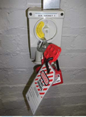
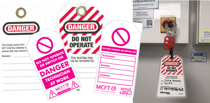
USE OF LOCKING OFF DEVICES, LOCKS AND LABELS (LOTOTO)
Part of achieving secure isolation is the taking of measures to ensure that power cannot be inadvertently restored before the work has been completed, and the covers replaced.
A range of locking off devices are provided; these range from locking off devices that can be used on circuit breakers through to devices that can be used on plug tops of various types.
MCFT technicians must follow the established MCFT Lock Out Procedure which is based on the following mantra and systematic steps:
LOCK OUT, TAG OUT, TRY OUT LOTOTO process:
Step 1: Prepare
Step 2: Shut Down
Step 3: Equipment Isolation
Step 4: Begin Lock-out & Tag-out
Step 5: Energy Isolation
Step 6: Verify Isolation
Step 7: Try-out
Step 8: Carry out Required Work
Step 9: Re-energization
Step 1 Prepare – Before the LOTOTO procedure can begin, a plan should be in place for the methods of control. The equipment should be fully assessed, and the correct lock-out materials selected. Workers within the area should be made aware that lock-out is occurring; this will help to prevent accidental re-energization.
Step 2 Shut down – Prior to the LOTOTO procedure taking place, the necessary equipment must be correctly shut down. This should be in line with manufacturers’ instructions to ensure the safety of employees.
Step 3 Equipment isolation – The isolation points on the equipment should be identified and partnered with an appropriate lock-out device prior to installing the devices. This will ensure that all necessary energy sources have the correct lock-out equipment required for blocking the energy source. Both primary and secondary energy sources should be identified and isolated at this stage.
Secondary Energy Sources
- More than one supply to a single piece of equipment – one 13amp supply for hot cupboard, another 13amp supply for gantry & heat lamps.
- Adjacent or bonded equipment (common on suited range).
Step 4 Begin lock-out – The lock-out devices should now be applied to fully isolate the equipment. The apparatus used as part of the LOTOTO procedure, such as Safety Padlock and identification tags, should be unique to the person applying them, and not be used for any other workplace activities. Storing lock-out equipment within a dedicated station will ensure they remain safe and accounted for. Once the devices have been safely applied, each should be carefully tagged. The tags will act as an identifier for the person who applied them, with information such as their name, picture and date and time of application on them. As a lock-out device should not be removed by any person other than those who applied them, the tags will ensure identification which will prevent removal and accidental restarting of the equipment by someone else.
Multiple Technicians: If multiple technicians are working on the same piece of equipment, or the same circuit, then a multi-hasp lock should be used. This is to prevent one operative re-energising the circuit when someone else may still be working on it.
Step 5 Energy isolation – The equipment should now be inspected to ensure all moving parts have ceased. This includes checking for areas which may have potential stored energy, such as those within pneumatic and hydraulic systems or spring-driven parts. These should be carefully blocked with the appropriate equipment to ensure unexpected movements do not occur during the maintenance or repair work.
Capacitor Discharge
Following standard practice, use your multimeter set on voltage and observe the discharge down to zero.
Step 6 Verify isolation – At this stage it is important to verify each aspect of the isolation. This includes ensuring all workers are kept clear of the area, lock-out devices are secure and correctly applied with associating tags, and that any moving parts have been blocked. Once this is completed, the try-out phase can begin.
Step 7 Try-out – The try-out phase of the procedure involves attempting to restart the equipment. Should the equipment have more than one energy source, it is important to thoroughly check each one has been safely isolated; this is especially true of equipment which may operate with timers and sensors, as these may restart unexpectedly. Once it has been confirmed all aspects of the equipment have been safely isolated and cannot be restarted, the controls should be switched off again. Should the equipment restart during the try-out phase, the LOTOTO procedure needs to restart and a full investigation into what did not work needs to take place. Refer to Safe isolation & Dead testing SOP – Dead testing procedure step by step guide.
Step 8 Work – As all areas of the equipment have been safely locked out and checked thoroughly, the necessary work can begin.
Step 9 Re-energization – After the necessary work has been completed the lock-out devices can be removed and the equipment restarted in line with manufacturers’ instructions. It is important to remember that these devices should only be removed by the person who applied them.
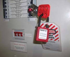
TAG IS VERY IMPORTANT
In 2012 in the build-up to the London Olympics, the Dutch team were based at Alexandra Palace. One of our senior refrigeration technicians was working on the remote compressor of a coldroom and, to that end, had attached a padlock to the isolator upstairs in the kitchen. The chef, who was not aware, asked the Catering Manager, Andrew McK****, why it was off – and Andrew, helpful chap that he was, forced the isolator to on, in spite of the padlock clearly attached.
Thankfully, at the time, our technician was not working on the 3-phase circuit but he took a belt and, running up the kitchen, challenged Andrew who, to this day, has never acknowledged that he did something wrong, stupid and very dangerous. Sadly, although he had tags, our technician had not attached on to his padlock. It’s possible that, even with an oaf like Andrew, he may have been dissuaded from forcing an isolator by an attached notice. Believe that apparently responsible people will behave like complete idiots – always tag the isolation.
SAFE ISOLATION PROCEDURES
For all work on LV electrical equipment or circuits, it is important to ensure that the correct point of isolation is identified, that an appropriate means of isolation is used, and that the supply cannot inadvertently be reinstated while the work is in progress. The conductors must be proved to be dead at the point of work before they are touched and where necessary caution notices should also be applied at the point(s) of isolation.
In the interests of avoiding inadvertent energisation, a good principle to adopt is that the point of isolation should be under the control of the person who is carrying out the work on the isolated conductors.
If alternative means of controlling the security of the isolation are adopted, such as the point of isolation being kept under the control of an appointed (authorised) person, these means should be equally effective at preventing inadvertent reinstatement of the supply.
The means of isolation can be an adjacent local isolation device such as a plug and socket outlet, fused connection unit, switch-disconnector, circuit breaker, fuse, etc. as appropriate, which is under the direct control of the competent person carrying out the work.
Note; When isolating the main source of energy, it is also essential to isolate any secondary sources such as standby generators, uninterruptible power supplies (UPS) and microgenerators.
A comprehensive list of devices that can be used for isolation is given in Table 537.4 of BS 7671: 2018, which is reproduced in Appendix B.
These devices can be used without further precautions provided there is no foreseeable risk that the supply could be reinstated by others prior to the work being completed by the competent person.
Note; Circuit-breakers conforming to BS EN 60898 are suitable for isolation and may be marked with the following symbol:
However, miniature circuit-breakers (MCBs) manufactured to earlier standards (such as BS 3871) are unlikely to be suitable for isolation.
Switchgear conforming to BS EN 60947-3 and circuit-breakers and RCDs conforming to BS EN 60947-2 are suitable for isolation if marked with the symbol shown above.
Where there is no such local means of isolation or where there is a risk of reinstatement of the supply, the circuit or equipment to be worked on should be securely isolated by one of the following methods:
1 - ISOLATION USING A MAIN SWITCH OR DISTRIBUTION BOARD SWITCH DISCONNECTOR
Isolation of equipment or circuits using the main switch or distribution board switch disconnector is the preferred method. The point of isolation must be locked off using a unique key retained by the person carrying out the work or the appointed person, and a caution notice attached to the point of isolation.
Where more than one operative is working on circuits supplied from an isolated distribution board, a multi-lock hasp can be used to prevent operation of the main isolator until such time that all persons working on the installation have completed their work and removed their padlocks from the hasp – the appointed lead technician has overall control and will be the person reinstating the power.
If locking-off facilities are not provided on the relevant switch, then a locked distribution board which prevents access to the switch-disconnector is acceptable provided the key is unique and is retained by the person doing the work or the appointed person – NOTE; if you are unable to lock off a circuit you MUST NOT carry out the task, escalate following the MCFT escalation process
2 - ISOLATION OF INDIVIDUAL CIRCUITS
Where it is intended that more than one person will be working on circuits supplied from a distribution board (multiple isolations) and a multi-lock hasp cannot be used to secure the main switch disconnector or the distribution board has to remain energised to supply other circuits, each circuit supplied from the distribution board on which work is to be carried out should be isolated by one or more of the following methods to prevent inadvertent reinstatement of the supply.
The principle is that each person carrying out such work should have control of their own point(s) of isolation and not rely on others, except an appointed person, to prevent deliberate or inadvertent energisation.
It is also preferable for an appropriate locking-off device to be used at the point(s) of isolation. Suitable labelling of the disconnected conductors using a caution notice is vital to prevent the supply being reinstated, particularly if other electricians are present.
2A - ISOLATION OF INDIVIDUAL CIRCUITS PROTECTED BY CIRCUIT‐BREAKERS
Where suitable circuit-breakers are used as the means of isolation, the relevant device should be locked-off using an appropriate locking-off clip with a padlock which can be opened only by a unique key. The key should be retained by the person carrying out the work or the appointed person. A caution notice should be attached at the point of isolation.
Note - The practice of placing insulating tape over a circuit-breaker to prevent inadvertent switch-on is not an adequate or acceptable means of securing the device in the OFF position. Such unsafe practice will not achieve compliance with the Electricity at Work Regulations 1989.
Some distribution boards are manufactured with ‘slider switches’ to disconnect the circuit from the live side of the circuit breaker. These devices should not be relied upon as the only means of isolation for circuits, as they do not meet the requirements for isolation and the wrong switch could easily be operated on completion of the work.
2B - ISOLATION OF INDIVIDUAL CIRCUITS PROTECTED BY FUSES
Where fuses are used, the removal of the fuse is an acceptable means of disconnecting the supply to an individual circuit for the purpose of isolation.
To prevent the fuse being replaced by others, the fuse should be retained by the person carrying out the work. A caution notice should be attached at the point of isolation.
Where lockable fuse inserts are not available, the following must be considered:
- Where removal of the fuse exposes live terminals that can be touched, a dummy fuse (that is a fuse carrier which is not fitted with a fuse link and which is clearly marked or coloured to make it conspicuous) should be inserted in the fuse way to cover live parts. When this is not possible, the incoming supply to the fuse will need to be isolated.
- A caution notice should be attached to deter inadvertent replacement of a spare fuse.
- In addition, if possible, the fuse board door or cover should be locked to prevent access as advised above under ‘Isolation using a main switch or distribution board switch disconnector’.
- Temporary disconnection of the incoming supply
NOTE -
For some types of work on existing installations, such as the replacement of main switchgear and consumer units, it is necessary for the distributor’s service fuses to be withdrawn in order to disconnect the incoming supply for the purpose of isolation.
Legally, service fuses can be withdrawn only by the electricity supplier or distributor, or by those they have expressly authorised to carry out such work.
Note: In TT systems, the incoming neutral conductor cannot reliably be regarded as being at Earth potential. This means that for TT supplies, a multi-pole switching device which disconnects the line and neutral conductors must be used as the means of isolation. For similar reasons, in IT systems, all poles of the supply must be disconnected.
In these circumstances, single pole isolation, such as by fuses or single-pole circuit- breakers, is not acceptable.
High Voltage Systems – MCFT do not work on HV systems. Maximum is 240V single phase and 415V three phase. A high voltage system carries more than 1000 Volts between conductors and 600 Volts between conductors and ground.
Caution Notices
In all instances where there is any risk that the supply could be reinstated, an appropriate warning/caution notice should be placed at the point of isolation. For distribution boards with ‘multiple isolations’, a single suitably worded notice on each distribution board, such as the example shown below, would suffice:
PROVING DEAD ISOLATED EQUIPMENT OR CIRCUITS
It is important to ensure that the correct point of isolation is identified before proving dead.
Where possible and safe to do so, this may include testing with the isolating device first in the ON position and then in the OFF position to establish that the equipment or circuit is under the control of that device.
Following isolation of the equipment or circuits and before starting work it should be proved that the parts to be worked on, and those nearby, are dead.
It should never be assumed that equipment is dead because an isolation device has been placed in the OFF position.
The procedure for proving dead should be by use of a proprietary test lamp or a two-pole voltage detector as recommended in HSE Guidance Note GS38, Electrical test equipment for use by electricians.
The use of multimeters, makeshift devices and noncontact voltage indicators (voltage sticks) is not advised for voltage detection as such use has caused accidents.
The test lamp or voltage detector should be proved to be working before and after use. This should be achieved preferably using a proprietary proving unit or an in-built self-test facility rather than by accessing live terminals. All line, neutral and protective conductors of the circuit should be tested and proved to be dead.
Electricians who regularly work on installations that have been energised should be equipped with devices for proving that conductors are dead. Electricians who may occasionally work on installations that have been energised should have ready access to devices for proving conductor’s dead.
Technicians must use electrical gloves supplied by the Company whenever testing to prove absence of voltage. A voltage presence test must be applied to both line and neutral conductors & to earth to safeguard against the risk of crossed or open circuit neutrals in the supply system. All mains supply conductors (e.g. phase(s) and neutral) of the isolated circuit/equipment must be tested. All other sources of electrical energy (e.g. capacitors) which are associated with the isolated circuit/equipment must also be tested prior to working dead.
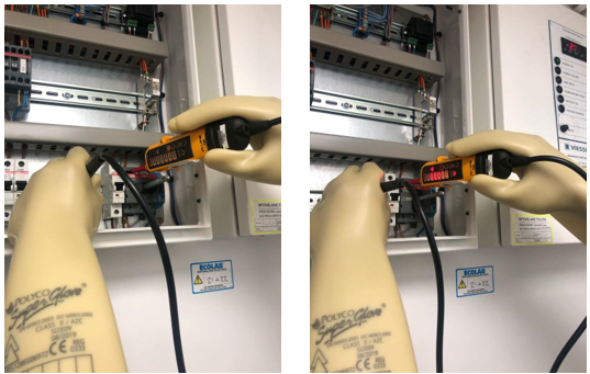
Dead Testing
The procedure for proving dead is to take the voltage indicator and check it against a known source, such as a proving unit, then test the equipment, before testing the voltage indicator against the known source again to prove the tester hasn't failed during testing.
Dead Testing Procedure: Step-by-Step Guide
- Isolate & lock off supply. (Following the LOTOTO SOP)
- Put both test leads from your voltage detector into the Proving unit all lights on your voltage detector should light up, so you know your tester is working.
- Using your voltage detector check between Live & Earth (No lights should light up if dead)
- Using your voltage detector check between Live & Neutral (No lights should light up if dead)
- Using your voltage detector check between Neutral & Earth (No lights should light up if dead)
- Put both test leads from your voltage detector into the Proving unit all lights on your voltage detector should light up, so you know your tester is working.
- Now you can be sure that the unit/system you are about to work on is DEAD.
Remember You need to test & re-test your test meter to prove for DEAD.
Technicians undertaking isolations for the purpose of working dead must always remain acutely aware of the isolation state of an item of equipment so that situations cannot arise where an technician is intending to work dead but through an aberration of mind thinks that the circuit is dead when in fact it is live. This possibility increases where the work or testing involves a series of isolation and re-energisations.
In addition, the systematic use of a voltage detector following each isolation and before commencement of invasive work should eliminate any risk of misunderstanding regarding the state of isolation – always prove the circuit is dead before commencing work.
WORKING DEAD
There will be no instance where a technician is touching the housing of a motor (or taking panels off) where the appliance has not been isolated. In the case that isolation is impractical (e.g. no access to isolator) you must not work on the appliance. Remember; LDL (live, dead, live) or 3-point testing – to verify your test instruments.
Live testing must only be carried out by competent technicians – assessed and signed off by Technical Leads.
When work has been completed and panels are back on, re-check earth to ensure no connections have been dislodged during operation.
Technicians involved in reactive fault finding and repair work may operate on a lone working basis. On occasions, such as when there are issues with gaining access to equipment, it may be necessary for a lone working technician to request assistance – if required, contact your TL and request a second person attend site, do not continue until the second person is on site.
WORKING DEAD – FAULT FINDING, TESTING AND REMEDIAL WORK
Planning For Fault Finding
Prior to working dead, the below must be considered:
- Confirm what the task is and that you understand what is required of you
- Complete MCFT dynamic Risk Assessment
- Check and prove tools and test equipment are functioning correctly
- Obtain information from the customer on the equipment’s use at the time of, or immediately before, the occurrence of the fault, and of any abnormalities observed by the client both immediately prior to the occurrence of the fault and at any time before
- Location and accessibility of the point of isolation
- Accessibility of the equipment and the available space for the purposes of carrying out the work
- Any equipment manufacturer’s service manual including the safety instructions, the component layout diagrams, circuit diagrams, etc.
- Identify circuits for testing, split into manageable sections for the purpose of testing
- Erect barriers and appropriate warning notices
TESTING LIVE – when and why
The Need For Testing Live
There will be occasions where electrical testing on dead equipment is not sufficient, these situations will be fault finding and testing of components during routine maintenance.
In these circumstances, the Electricity at Work Regulations may permit live electrical testing to be contemplated subject to defined stringent conditions. http://www.hse.gov.uk/pUbns/priced/hsr25.pdf
MCFT Limits Of Acceptability For Live Electrical Work
Technicians testing live must not undertake any:
- work involving direct contact with live conductors forming part of any equipment having voltages above 50 V a.c. or 120 V d.c.
- live electrical testing on equipment having voltages above 240 V single phase or 415 V three phase
- undertake live repair work
Decision Making On Live Electrical Testing
MCFT technicians shall avoid live testing where possible. If this cannot be achieved, technicians shall not contemplate or engage in live testing unless:
- a full assessment of the risk involved is undertaken
- suitable precautions are taken to prevent injury
- the precautions set out in this document are followed
Instructions on the interpretation of the above broad requirements on whether live electrical testing is admissible are contained within this Work Manual and the principles underpinning the decision-making process are illustrated below:
Responsibilities Of MCFT Technicians
Responsibility for following this Work Manual is delegated to the technician on site at the time. Live testing is not permitted in circumstances where the testing can be reasonably undertaken with the equipment isolated. This restriction will apply to most fault-finding situations. But it is recognised that there are circumstances where it becomes difficult to pinpoint a fault when solely working dead.
In the event of a site technician requiring any additional advice or clarification of any part of this Work Manual, the technician must contact their manager for assistance.
PLAN & PROCEDURE FOR LIVE ELECTRICAL TESTING
Once it has been determined that live testing is appropriate, before any testing is undertaken, the technician must prepare a live testing plan and must have completed a full risk assessment – the technician must re-evaluate the risk assessment during the course of the task if the dynamics change. The aim of the plan is to minimise the amount of live testing required, and to ensure that the risks involved will be controlled and reduced to the lowest possible level. The plan must consider all the available information on the nature of the task, this information shall be used to identify the likely place of testing and therefore minimise the scope of any live electrical testing and would include:
- Information provided in the initial notification to the technician
- External signage from the equipment concerned observed by the technician
- Information from the customer on the equipment’s use at the time of, or immediately before, the occurrence of the fault, and of any abnormalities observed by the customer both immediately prior to the occurrence of the fault and at any time before
- Previous product knowledge of faults and spare part demands
- The equipment manufacturer’s service manual including the safety instructions, any live testing instructions, the component layout diagrams, circuit diagrams, etc
- Consideration for thermal cut-out devices and magnetic interlocks within the electrical circuit
- The location and accessibility of the point of isolation
- Confirmed plan for emergency isolation during testing - assign a buddy; in emergency then ability to call for help, understanding of basic rules and the ability to turn off the power supply
- The presence of any extraneous earthed metal work must be avoided for the purpose of human contact – must be a minimum of 1.4m away and a minimum of 1m away from any surface, recognising that the frame of the equipment will be earthed through the supply cable
- The accessibility of the equipment and the available space for the purposes of carrying out electrical testing – no stretching or over-reaching – adopt a good body position (if a chef drops a pan which way are you going)
- The location of the live terminals that will be exposed and any precautions that can be taken to prevent the possibility of inadvertent contacts occurring
- How the available information can lead to the possible splitting the circuits into sections for testing so that part of the testing can be undertaken dead and the need for live testing eliminated or minimised
- How Company approved current information can be used instead of live probes for collecting information that assists in identifying the location of faults
- Noting the physical features of the location in respect of planning for the erection of barriers and demarcations to prevent unauthorised persons from entering the testing area
- Confirmation of test equipment functionality and PPE condition (electrical gloves)
Use Of An RCD When Undertaking Live Testing On Equipment Supplied From A 13a Socket
Technicians must install a Company supplied temporary RCD trip prior to undertaking live testing on equipment connected to a 13A socket. The RCD trip must be tested immediately after being plugged into the socket using the integral “Test” button.

Prevention Of Unauthorised Persons From Entering A Live Testing Area
Before commencing live testing, the technician must establish barriers to prevent unauthorised persons from entering the danger zone and must demark barriers with Company supplied warning signs. Barriers can be the folding type or hi-visibility warning tape secured around the workspace.
The live testing area must not be left unattended.
MCFT technicians are instructed to be aware of the presence of neighbouring earthed extraneous metal work when undertaking live testing and must avoid contact with these earthed objects – there must be a minimum of a 1.4m in the work space from metal work.
It is recognised that most of the chassis and external casings of equipment is connected to earth through the supply cable and are often connected through extraneous metal conducting parts to other such items of equipment.
Personal Protective Equipment - PPE
- MCFT Technicians must always wear appropriate PPE
- Test the condition of PPE before use – replace faulty PPE
- Always inspect electrical gloves before use – test for holes, rips, tears, deterioration
- The above is the responsibility of the individual
RESTORATION OF SUPPLY ON COMPLETION OF WORKS
On completion of the work, technicians must ensure that the equipment is fully/correctly assembled, all tools and instruments have been removed, and covers have been replaced.
Following reassembly and inspection, a portable appliance test or in-service electrical test in accordance with the latest edition of the IET Code of Practice for in-service inspection and testing of electrical equipment should be carried out to ensure the safe operation of the equipment – results must be recorded on the job sheet. The required tests, in sequence, are;
- Earth continuity test
- Insulation resistance test
If the equipment has passed the above tests satisfactorily then the power can be restored to the equipment. If this is via a BS1363 plug top the socket outlet must be proved safe by the socket outlet tester prior to commencing work. Once powered up a functional test should be carried out prior to returning the equipment to service.
CARRYING OUT ELECTRICAL SAFETY TESTS
Earth Continuity Limit
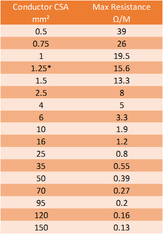
The limit for the Earth Continuity Test is (0.1 + R) Ω. Where the ‘R’ value is the resistance of the protective conductor (earth wire) within the supply cable. In practice when PAT testing, measuring the actual resistance of the earth wire within the cable is impractical, therefore the ‘R’ value is usually calculated using Table A5.1 in appendix 5 of the IET Code of Practice.
Table A5.1 in appendix 5 of the IET Code of Practice, page 107, gives values for the nominal resistance of the protective conductor per metre length for various lengths of cable, including those fitted as supply leads to appliances. It only applies to conductors having Class 5 or Class 6 construction (Ordinary flexible or flexible weave, respectively).
The cable size, cross sectional area (CSA), is usually marked on the outer sheath. For example, a 3-core cable with a CSA of 1.0mm² per conductor. Therefore, the maximum earth continuity limit for an appliance fitted with 3m of this cable would be: (0.1 + (3 X 0.0195)) Ω = 0.16Ω.
Please note all the brackets are required in this equation. Also round up.
Please note:
The earth continuity threshold is Below (0.1 + R) Ω. This is as per the IET Code of Practice for In-service Inspection & Testing of Electrical Equipment, 5th Edition
High Earth Readings
Earth continuity readings higher than the (0.1 + R) Ω limit are often due to problems with the test procedure, rather than the appliance itself. Check and re-check, test and re-test.
Insulation Resistance
The recommended test voltage for performing insulation tests is 500 V DC. The instrument used should be capable of maintaining the test voltage when applied to the insulation of the equipment under test.
If the insulation test indicates a zero or a very low value, it is an indication that the equipment being resistance tested may have a fault. The fault should be rectified before any further testing. Some types of equipment may have a filter networks or transient suppression device, such as surge protection devices (SPDs) equipment of this type may give values of insulation resistance below normally accepted levels by design, preforming the insulation resistance test at a reduced voltage, usually 250 V DC, is another option for testing this type of equipment.
Insulation resistance is normally measured by applying a test voltage of 500 V DC between the live conductor & the protective conductor & measuring the resistance.
Some equipment may not be suitable for insulation resistance testing at 500 V DC, particularly equipment with sensitive components, such as dimmers. In such cases, the manufacture of the equipment should be consulted before proceeding with the 500 V insulation test & before conducting alternate test options, such as a reduced insulation resistance test at 250 V DC (which will not stress the components any more than mains voltage does).
Touch Test (voltstick)
- Touch Voltage – How to test using a Fluke 1AC-E II
- Short press the on/off button for light & sound
- Long press the on/off button for light only
- Test device on a known source
- Test all surfaces adjacent to the working area to include the appliance being worked on.
- If whilst touching the appliance/local surfaces you get a permanent light at the tip & /or sound, this indicates voltage present – immediately look for local isolation.
- If there is no permanent light, voltage not indicated, proceed with caution.
- Test device on a known source. (to make sure still working)
This piece of test equipment is only to be used for this test & not for DEAD testing
Earth Continuity
- Earth continuity Between appliances - How to test using a Fluke T5-1000
- Set your meter to Ohms Ω
- Test between the metal surfaces of 2 x appliances to check there is continuity of the earth.
- Earth continuity - How to test using a Fluke T5-1000
- First make sure the system is isolated/unplugged
- Set your meter to Ohms Ω
- Test between the incoming earth supply/earth pin on the plug top and the case of the unit. There is no button to press using this tester (we are looking for a reading below (0.1 + R) Ω
- Earth continuity - How to test using a Kewtech K35
- First make sure the system is isolated/unplugged
- Set your meter to Ohms Ω
- Set the dial to 20 Ohms Ω
- Test between the incoming earth supply/earth pin on the plug top and the case of the unit by pressing the button (we are looking for a reading below (0.1 + R) Ω)
- Earth continuity - How to test using a Fluke 1587
- First make sure the system is isolated/unplugged.
- Set your meter to Ohms Ω.
- Change the range to 6 0 K (This is to give a reading to 2 decimal places)
- Test between the incoming earth supply/earth pin on the plug top and the case of the unit. There is no button to press using this tester (we are looking for a reading below (0.1 + R) Ω
- Earth continuity - How to test using a Uni-T UT533
- First make sure the system is isolated/unplugged.
- Set your meter to Ohms Ω.
- Power on the Uni-T – This will set Auto Range
- Test between the incoming earth supply/earth pin on the plug top and the case of the unit. There is no button to press using this tester (we are looking for a reading below (0.1 + R) Ω
Insulation Resistance
- Insulation Resistance - How to test using a Kewtech K35
- First make sure the system is isolated/unplugged
- Set your meter to 250V.
- Set the dial to 2000 M Ω.
- Test between Live & Earth on the outgoing side of the isolator (remembering that the incoming side will still be live) or the live pin and Earth pin of the plug top, you also need to test both sides of any contactor fitted in the system Live to earth. By pressing the button, we are looking for a reading above 1M Ω but would suggest that anything below 10M Ω needs investigating.
- Insulation Resistance - How to test using a Fluke 1587
- First make sure the system is isolated/unplugged.
- Set your meter to Insulation Resistance
- Set the range to 250V.
- Test between Live & Earth on the outgoing side of the isolator (remembering that the incoming side will still be live) or the live pin and Earth pin of the plug top, you also need to test both sides of any contactor fitted in the system Live to earth. By pressing the button either on the test probe or the test meter, we are looking for a reading above 1 MΩ but would suggest that anything below 10 MΩ needs investigating.
- Insulation Resistance - How to test using a Uni-T UT533
- First make sure the system is isolated/unplugged.
- Set your meter to Insulation Resistance.
- Power on the Uni-T.
- Set the range to 250V.
- Test between Live & Earth on the outgoing side of the isolator (remembering that the incoming side will still be live) or the live pin and Earth pin of the plug top, you also need to test both sides of any contactor fitted in the system Live to earth. By pressing the button either on the test probe or the test meter, we are looking for a reading above 1 MΩ but would suggest that anything below 10 MΩ needs investigating.
Good Earth Test (Ze. The resistance of the circuit line conductor, R1.)
- Good earth test – How to test using a Martindale EZ650 – THIS IS A LIVE TEST.
- You can either use the 13A plug lead for testing sockets or the 3-wire lead to test fixed appliances. (Both leads supplied)
- plug in the socket tester to the appropriate socket, it will do a self-test first & then will show you whether it is wired correctly, whether there is a fault in the wiring & what the earth loop impedance is (Green is good Red is not)
- Using the 3-wire lead for fixed appliances connect the green clip to earth, black to neutral and red to live in that order (Circuit needs to be live), it will do a self-test first & then will show you whether it is wired correctly, whether there is a fault in the wiring & what the earth loop impedance is (Green is good Red is not)
Dead Testing
- Proving for dead: how to test using a FlukeT90 & a Socket & See SP200 Proving unit
- Isolate & lock off supply.
- Put both test leads from the T90 in to the SP200 Proving unit all lights on T90 should light up, so you know your tester is working.
- Using the T90 check between Live & Earth (No lights should light up if dead)
- Using the T90 check between Live & Neutral (No lights should light up if dead)
- Using the T90 check between Neutral & Earth (No lights should light up if dead)
- Put both test leads from the T90 in to the SP200 Proving unit all lights on T90 should light up, so you know your tester is working.
- Now you can be sure that the unit/system you are about to work on is DEAD.
- Proving for dead: how to test using a Martindale VIPD138-S Safety Voltage Indicator & Proving unit.
- Isolate & lock off supply.
- Put both test leads from the T90 in to the SP200 Proving unit all lights on T90 should light up, so you know your tester is working.
- Using the T90 check between Live & Earth (No lights should light up if dead)
- Using the T90 check between Live & Neutral (No lights should light up if dead)
- Using the T90 check between Neutral & Earth (No lights should light up if dead)
- Put both test leads from the T90 in to the SP200 Proving unit all lights on T90 should light up, so you know your tester is working.
- Now you can be sure that the unit/system you are about to work on is DEAD
Remember you need to test & re-test your test meter to prove for DEAD
Contact Resistance
The contact resistance between the test lead and appliance case, or the appliance plug and test instrument, can significantly increase the measured resistance. The low current earth test is particularly susceptible to the effects of contact resistance because it has less power to break through any oxidation layer on the plug or case. Cleaning the earth pin of the plug with an abrasive paper and making sure the test probe is making a good contact with the metal surface will often reduce the earth continuity reading. Pay particular attention to where the test probe or clip is placed. For example, when testing a kettle, putting the test clip on a heating element without breaking through the lime scale will increase the resistance significantly.
Oxidation layer on plug will increase contact resistance:
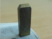
Test Lead
The resistance of the test lead should also be considered. The resistance of the test lead can be measured by connecting both test leads directly together. Some test instruments allow the resistance of the lead to be nulled.
Casual or Fortuitous Contact
The IET Code of Practice describes a situation where a Class I item may have metal parts that are not directly earthed but will provide a continuity reading because they are in contact with an earthed metal part. Connecting the test lead to metal that is not directly earthed will usually give a higher reading. For example, the case of a fridge is earthed because it contains the compressor, light, and thermostat etc. The fridge door however does not usually have an earth connection. Placing the test lead on the door will provide an earth reading as it is connected to the earthed case by a metal hinge. In this example the fridge door is in ‘casual or fortuitous contact’ with an earthed metal part. Connecting the test lead to the door is likely to give a higher reading than if connected to the main case of the fridge.
“Unearthed metal may be in casual or fortuitous contact with the earthed metal. A continuity test made to this ‘unearthed’ metal may give misleading results” IET Code of Practice 10.5.2 note 7
EQUIPMENT PROVIDED
Test Equipment
- Kewtech meter
- Fluke T5-1000
- GS38 test leads
- Uni-T UT533
- Martindale VIPD138-S Safety Voltage Indicator & Proving Unit
- Fluke T90
- Proving unit
- Martindale EZ650
HSE
Guidance Note GS38 on Electrical Test Equipment.
PPE – Personal Protective Equipment
- lectrical Gloves - Gloves must be minimum Class 00 and conform to EN60903
- Always inspect gloves before use – test for holes, rips, tears, deterioration
- Discard damaged gloves
- Barriers – ‘A’ frame barrier and Hi-Visibility tape
- Signage
- Lock-out Tag-out Kit
- Goggles
Appendix A - First Aid
It may not be immediately clear, but if you think someone is suffering from electric shock, approach with extreme caution.
The first step is to separate the person from the source of electricity as quickly as possible. The best way of doing this is to turn off the supply, for example, by unplugging the appliance or by turning the isolator.
If this isn’t possible, then try to remove the source of electricity from the person using a piece of insulating material, such as a length of wood or a wooden broom.
NEVER touch the person receiving the electric shock, or you could suffer one too.
After removing the person from the source of electricity, if the person is unconscious call for an ambulance immediately. Only those with the necessary knowledge and skill should carry out first aid.
Where the person is conscious and seems well, it is still advisable to monitor their condition, as the effects of an electric shock may not be immediately obvious. In worst case conditions, an electric shock may lead to a condition known as electroporation, where cells within the body rupture, leading to tissue death. Additional problems might include deep-seated burns, muscle damage and broken bones.
For support and assistance with electric shock and electric burns refer to the below link https://www.nhs.uk/conditions/first-aid/
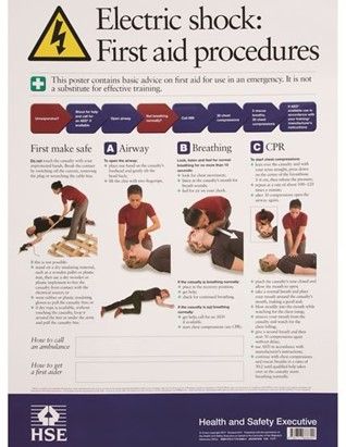
Appendix B - Guidance on selection of protective, isolation and switching devices
Guidance on the selection of protective, isolation and switching devices, reproduced from BS 7671:2018 table 537.4
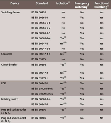
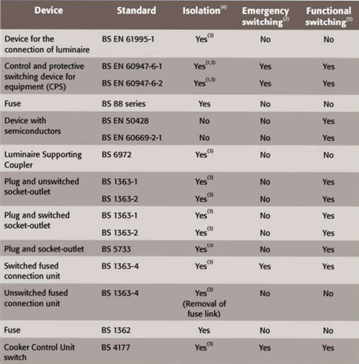
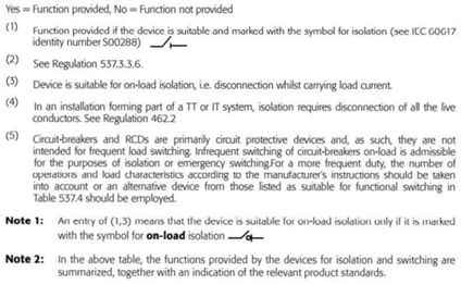
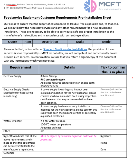
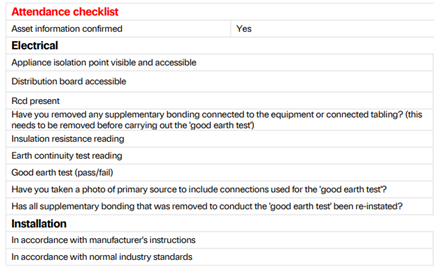
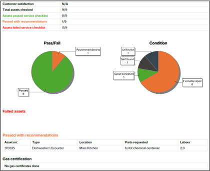
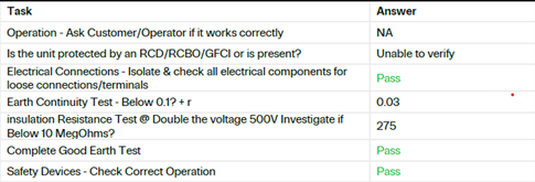
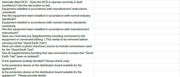
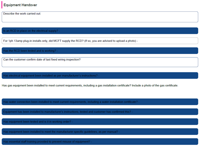
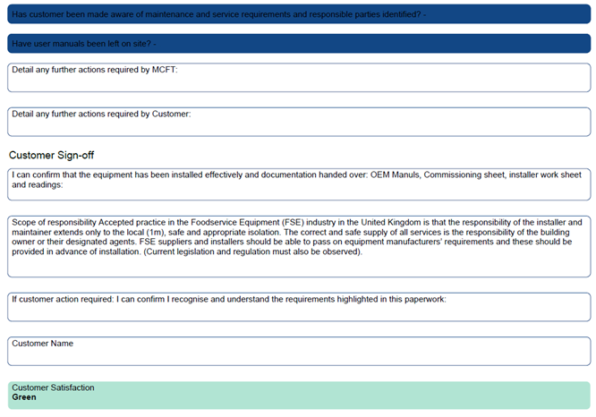
| Equipment / Instrument | Calibrator / Inspector |
|---|---|
| Multimeter | Re-Cal |
| Clamp Meter | Re-Cal |
| Leak Detector (Fridge, Gas, Microwave) | Re-Cal |
| Fridge Scales | Re-Cal |
| Digital Thermometer | Re-Cal |
| Kane Gas Analyser | Kane |
| Kane Gas Leak Detector | |
| Socket Tester Kit | Checked in-house by Matt Alderton |
| Fire Extinguishers | FAFS |
| PAT Testing (Hoover, vac pump etc) | Annually at Comms meetings, any missed arranged locally to tech |
Appendix F – Technical Committee
Chair – David Meacock – Group Director of Engineering
UK Lead – Matt Alderton
EU Lead – Markus Schemburg
GCC Lead – Ben Harnett
PH Lead – Alex Wilson
| Electricity | Gas | Wash / Water | Fridge | |
|---|---|---|---|---|
| Technical Leads | Matt Alderton | Like Embling | Chris Pyle | Colin Tomlinson |
| Kevin Foy | Stuart D Ford | Ben Harnett | ||
| Professional Body | IET | IGEM | WaterRegsUK (WIAPS) | IOR |
| Regulatory Authority | IET | Gas Safe | Local water Authority (DEFRA) | Refcom |
| Safety (emphasis) | Lead | Field | Office | |
| David Meacock | Matt Alderton | George Banks | ||
| Deputy | Jack Kay |
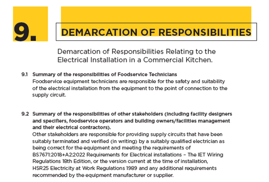
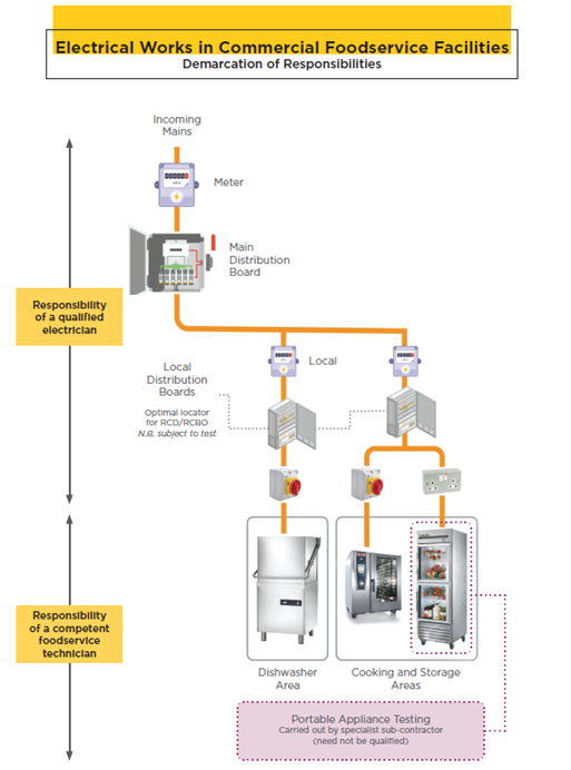
By reading and acknowledging this document, you confirm that you have read and understood the content. By reading and acknowledging this document on Breathe, you confirm this is the equivalent to your signature, this will be date stamped and there will be a requirement for you to acknowledge this on an annual basis.